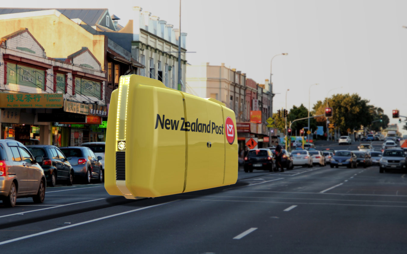
Project: SlimRide - Public transport system (PRT).

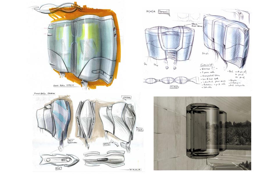
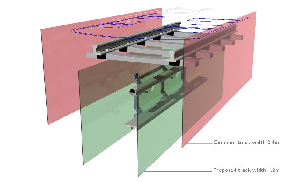
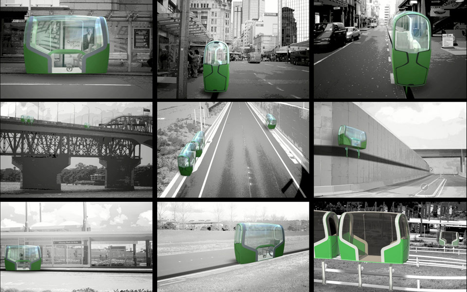
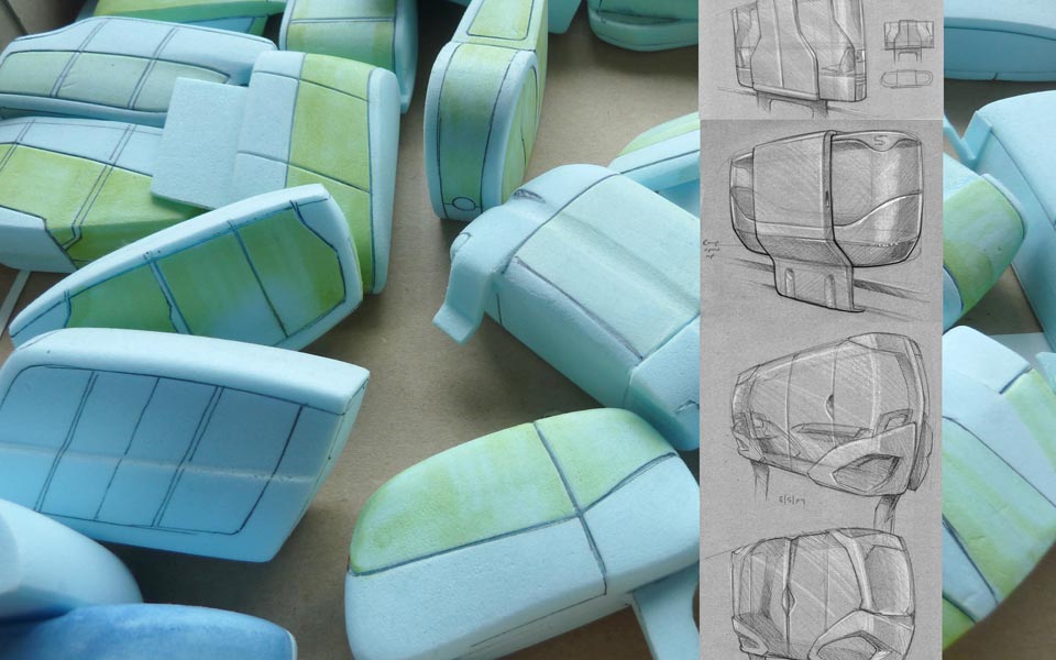
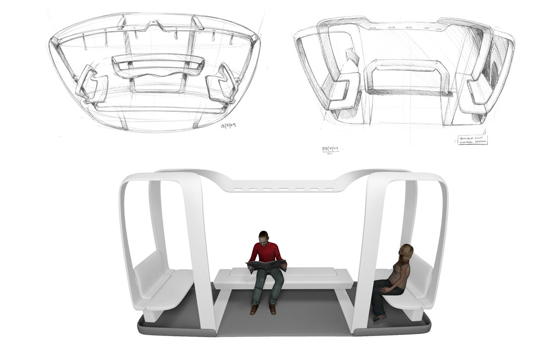
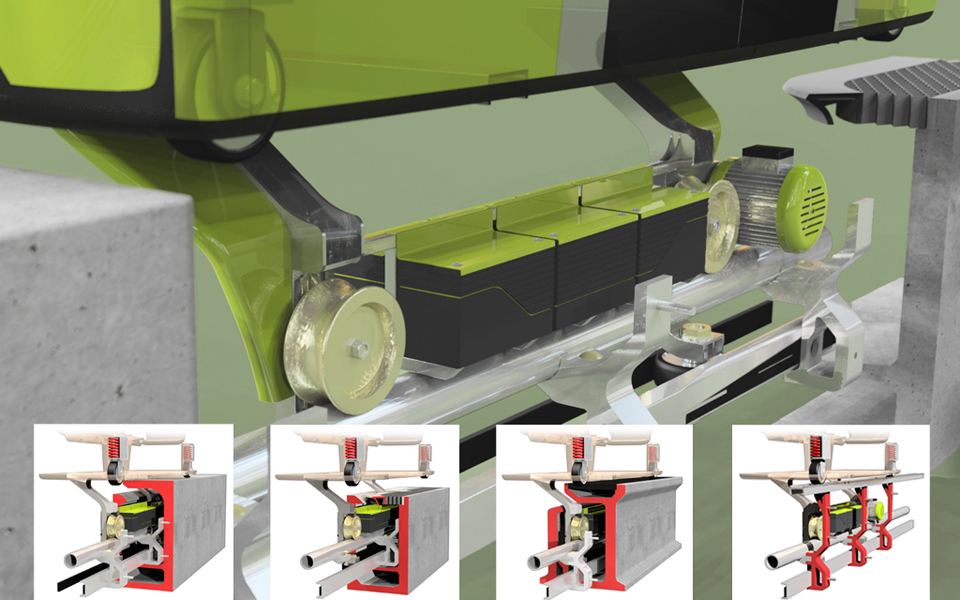
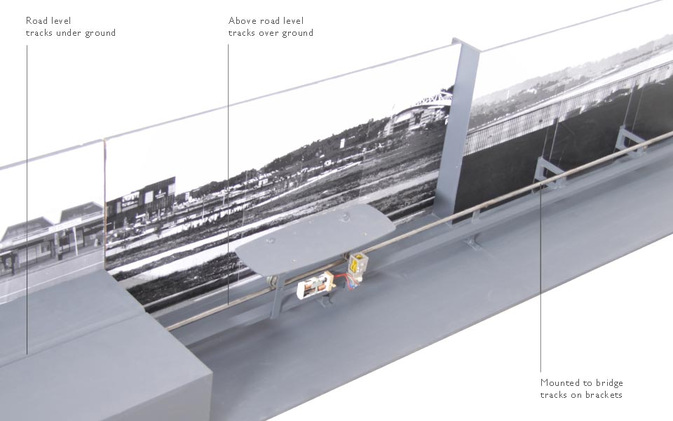
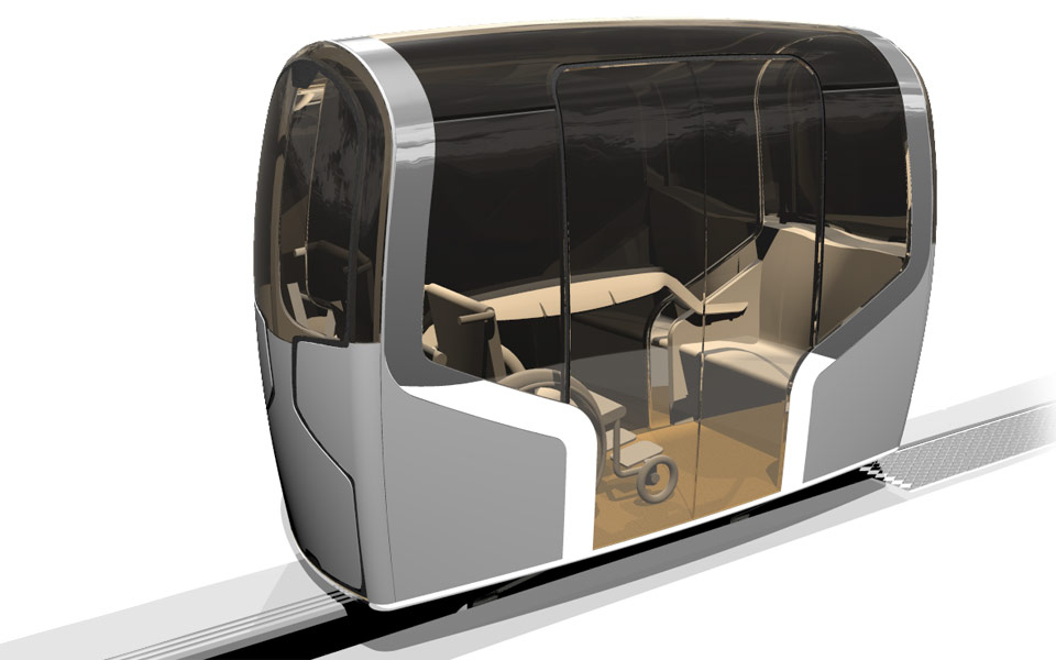
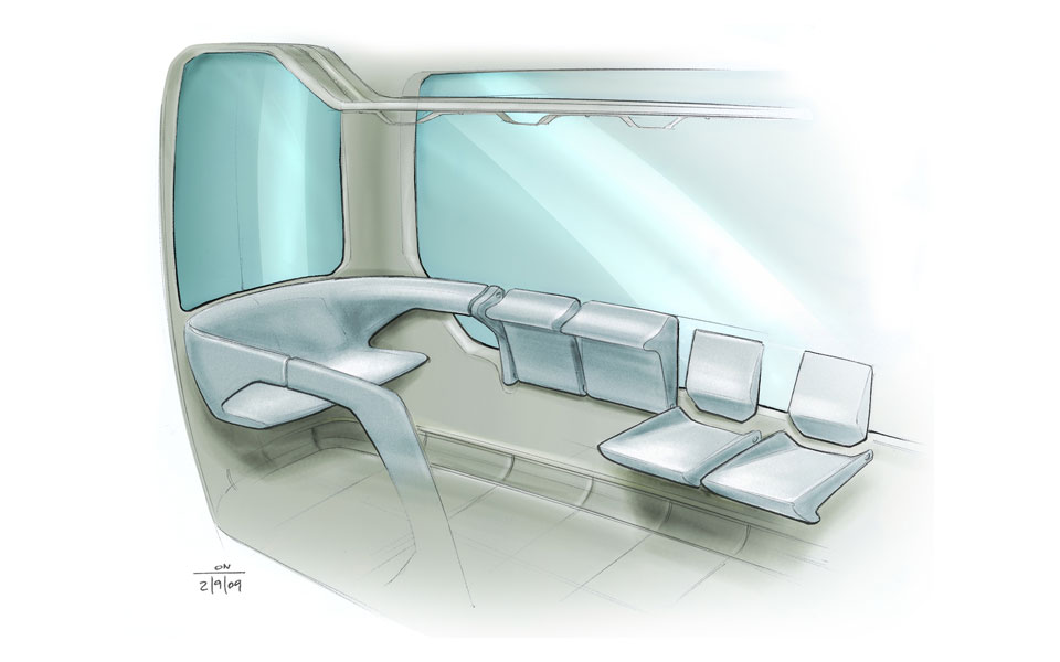
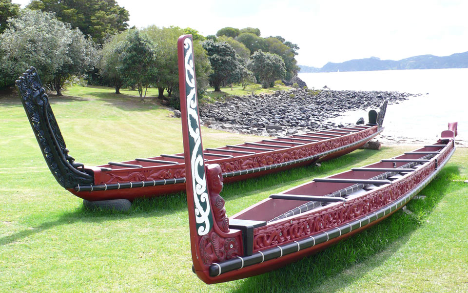
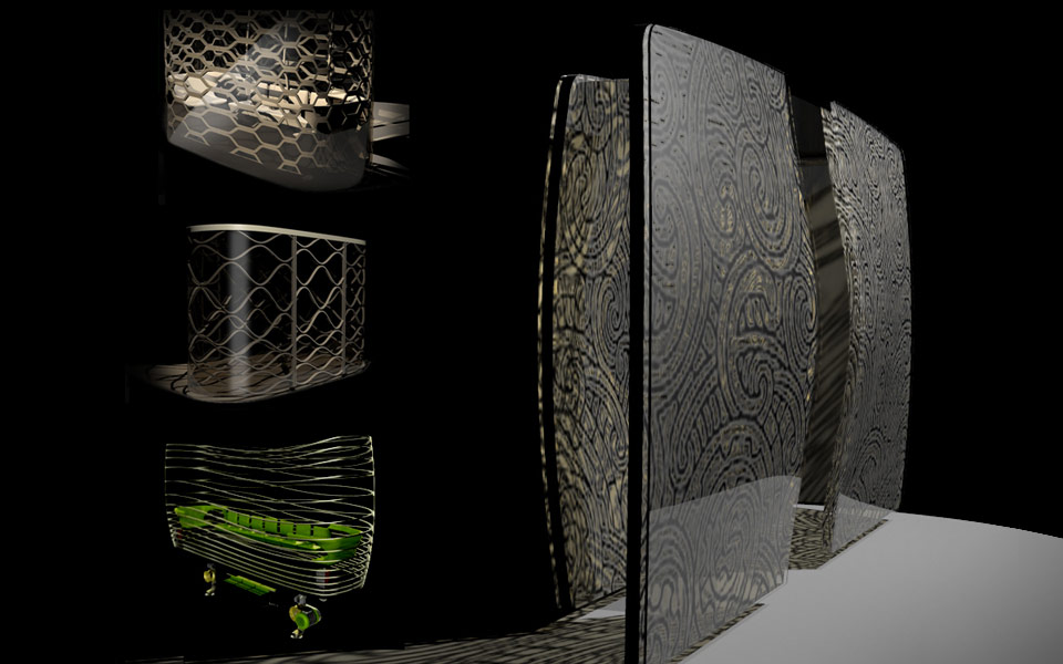
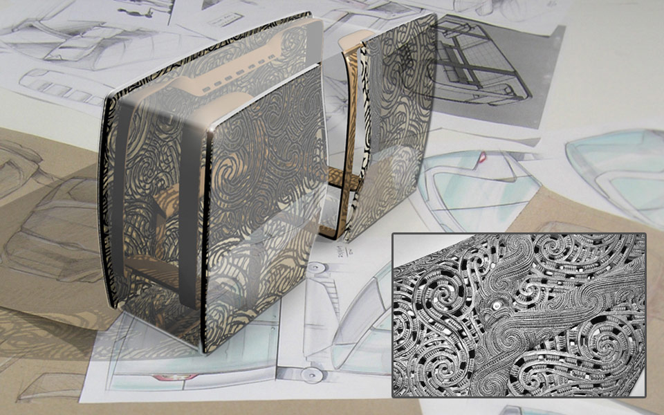
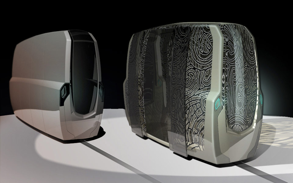
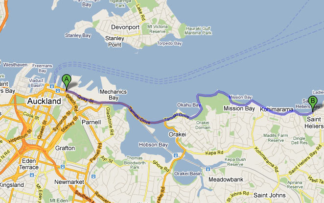
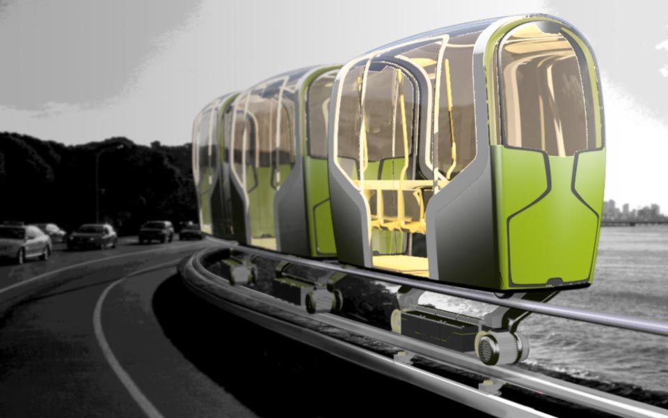
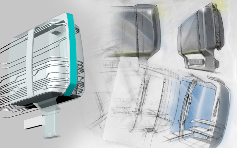
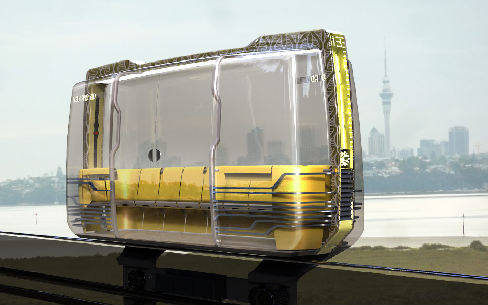
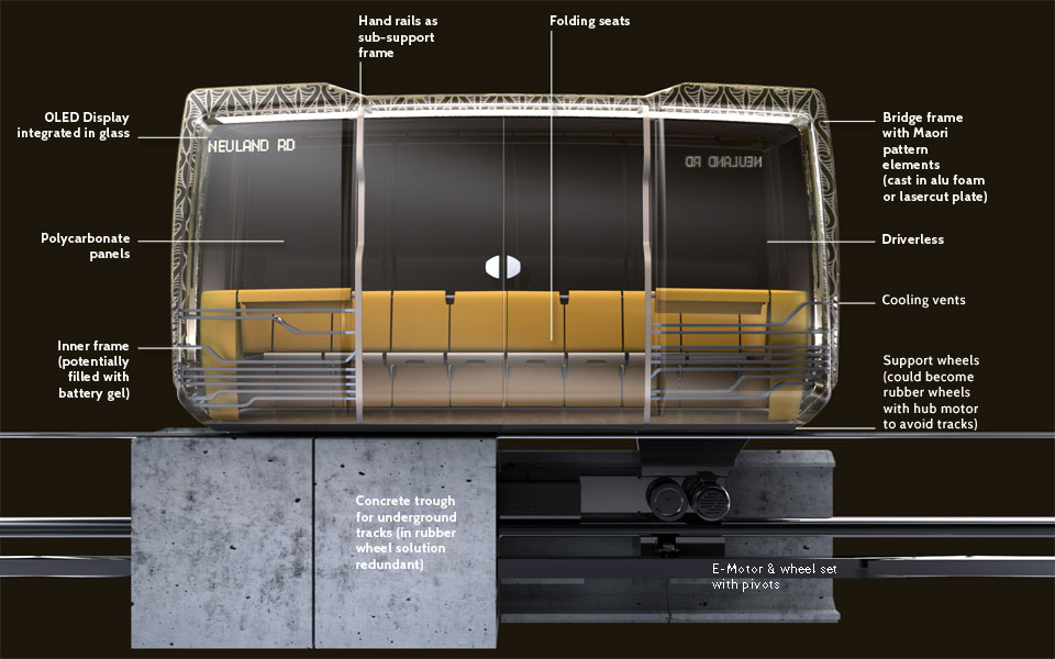
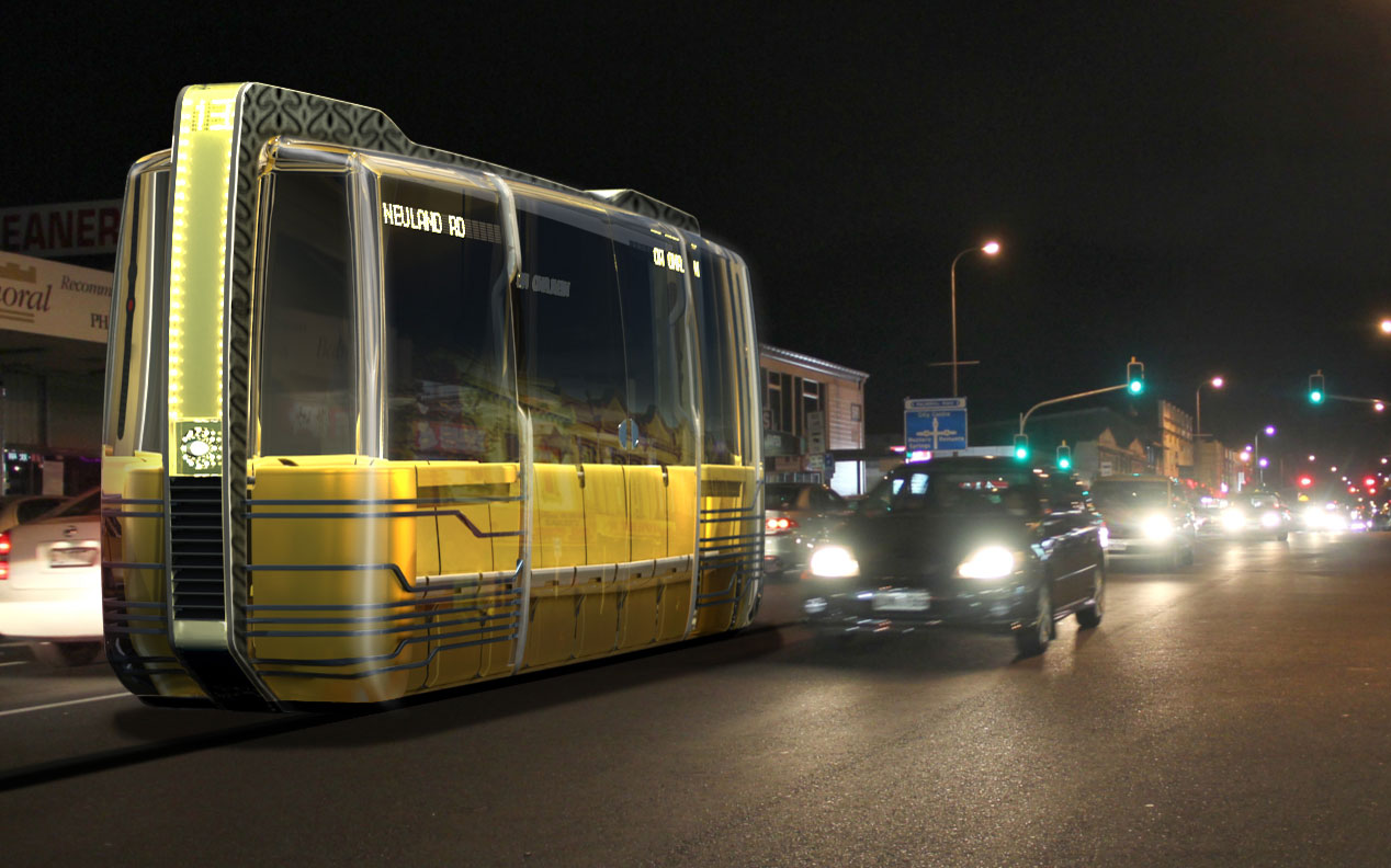
The conceptual study adressed Auckland City transport issues and resulted in a driverless, slim rail system concept with an extremely narrow footprint that would suit multiple infrastructures using limited space more sustainably. The project investigated application of innovative rail technology, desirability of such a public transport solution for a car-focused audience and how to make it iconic and implement local cultural references. An iterative design approach was tested, developing interior and exterior ideas independently to a high level before merging matching idea pairs - broadening design scope.

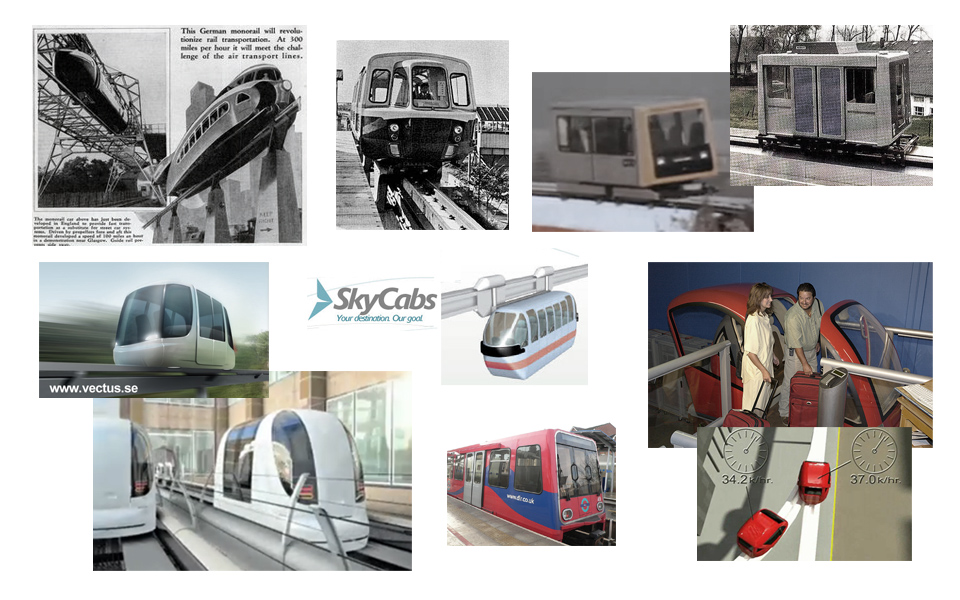
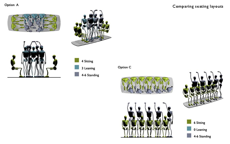
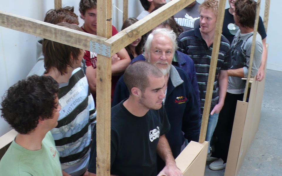
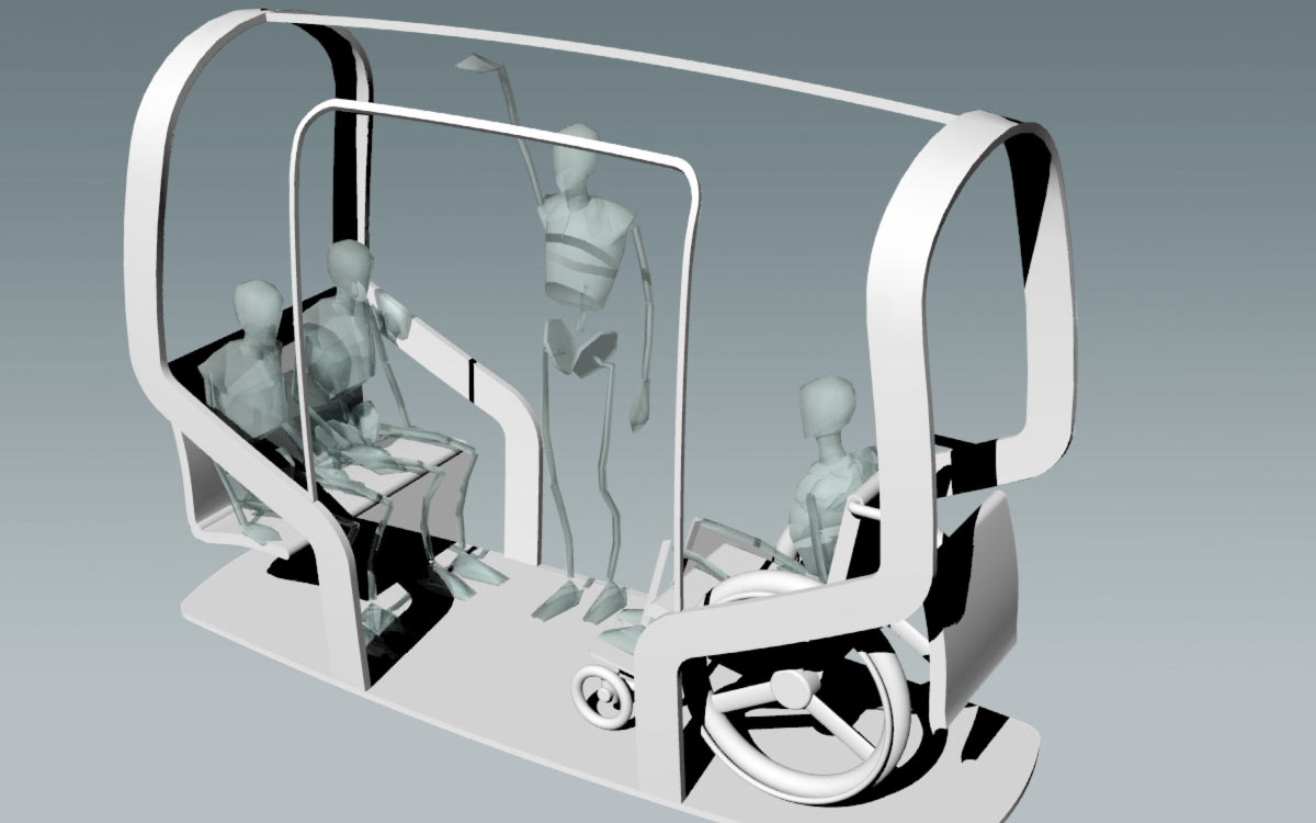
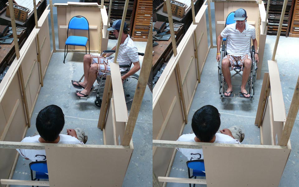
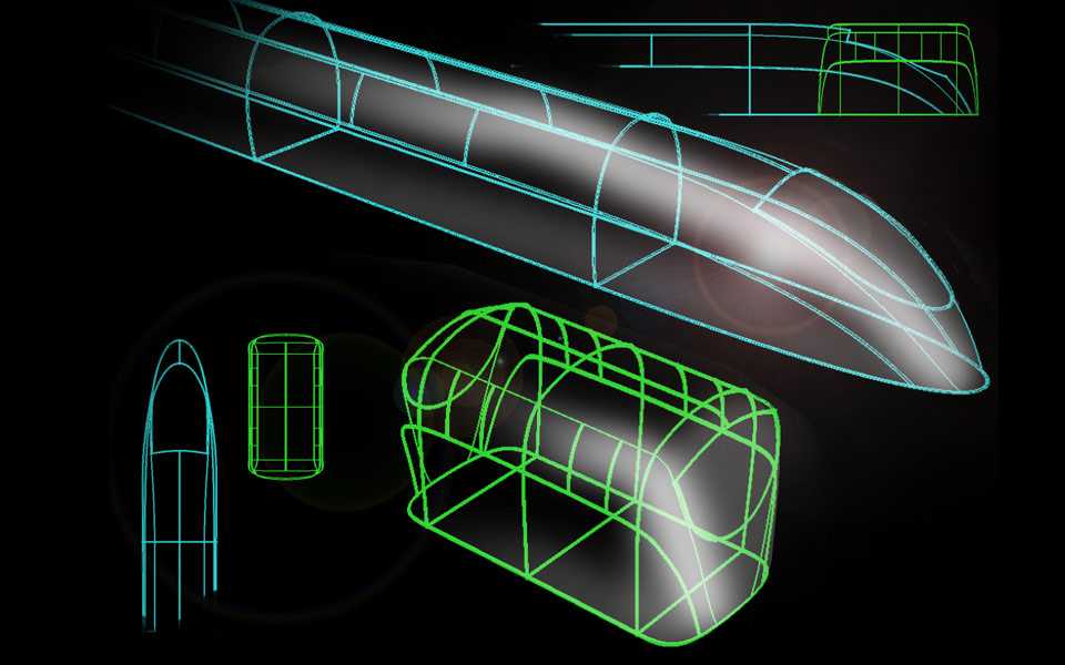
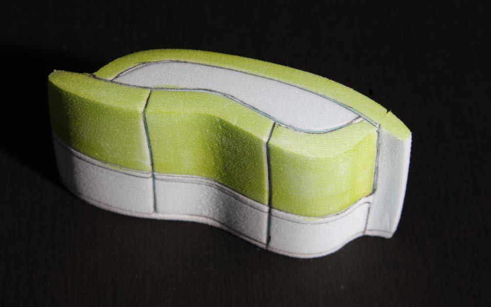
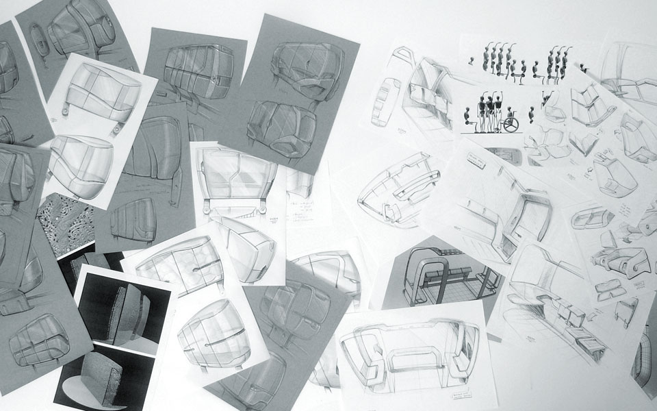
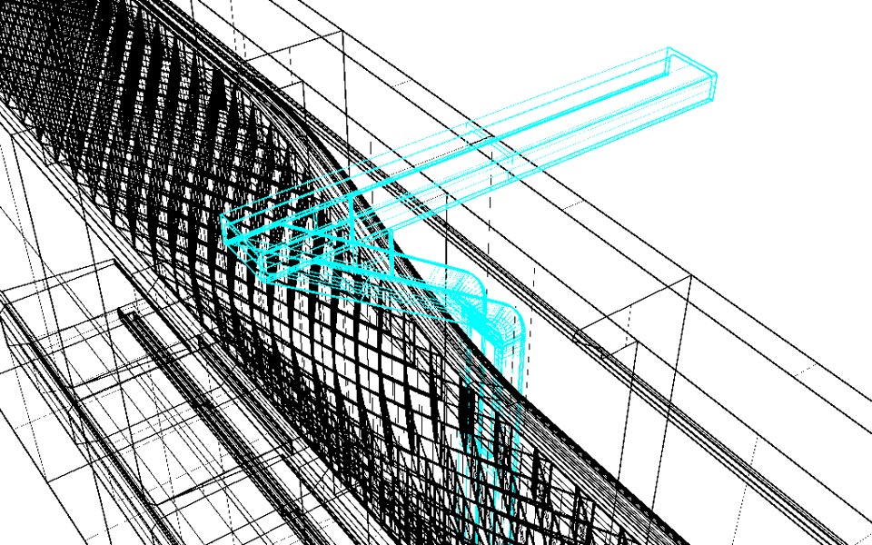
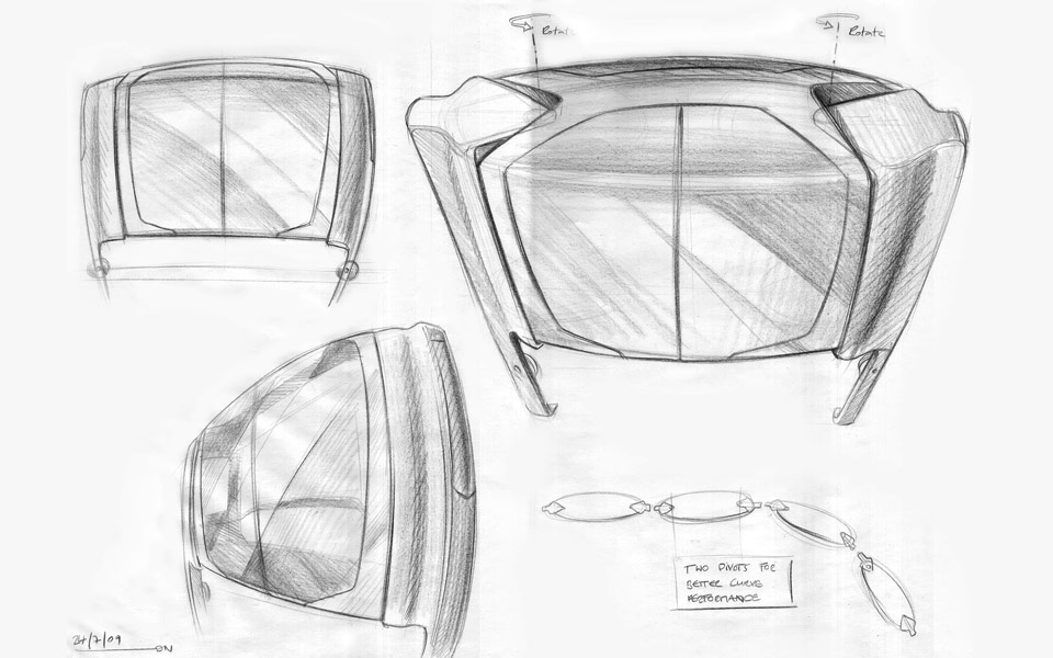
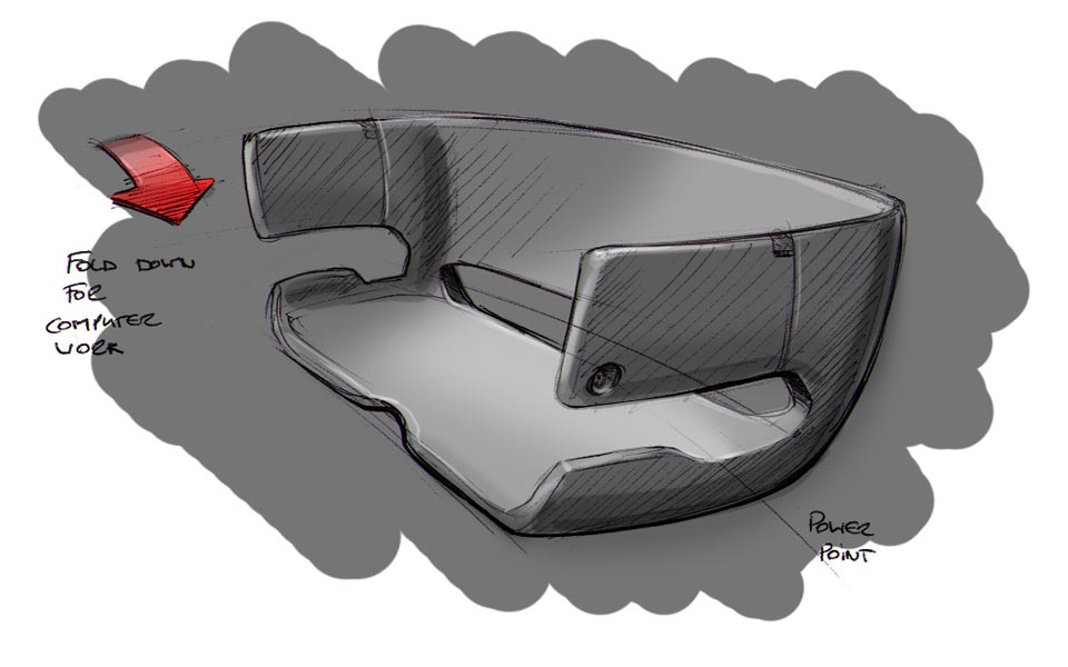
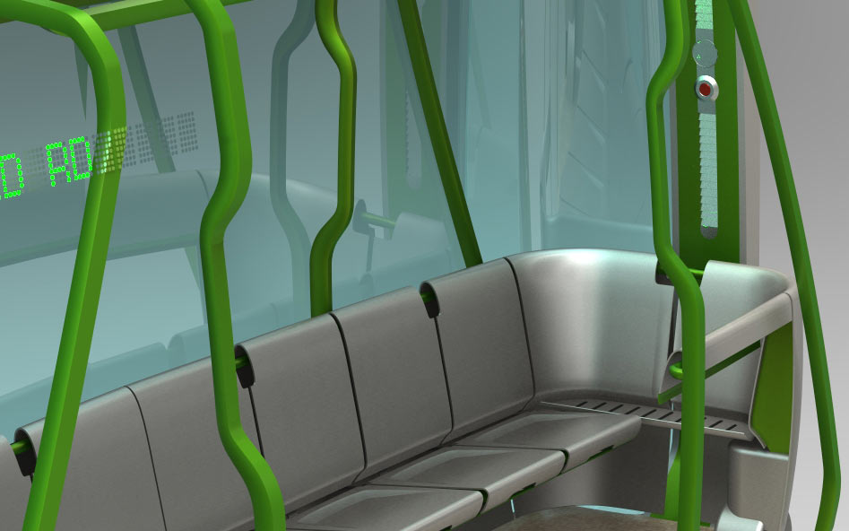
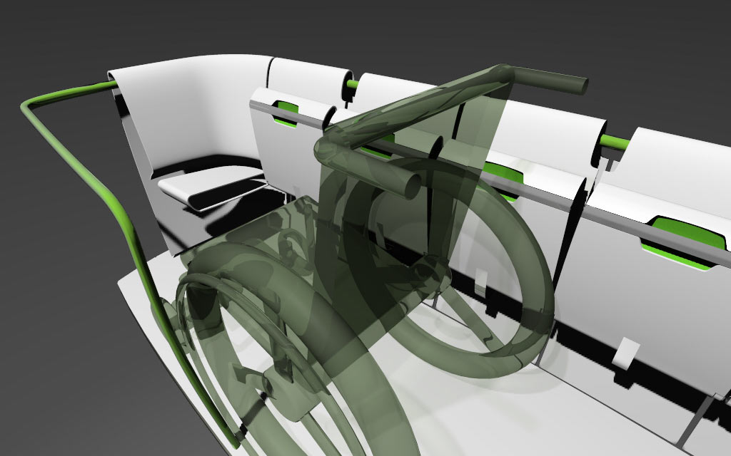
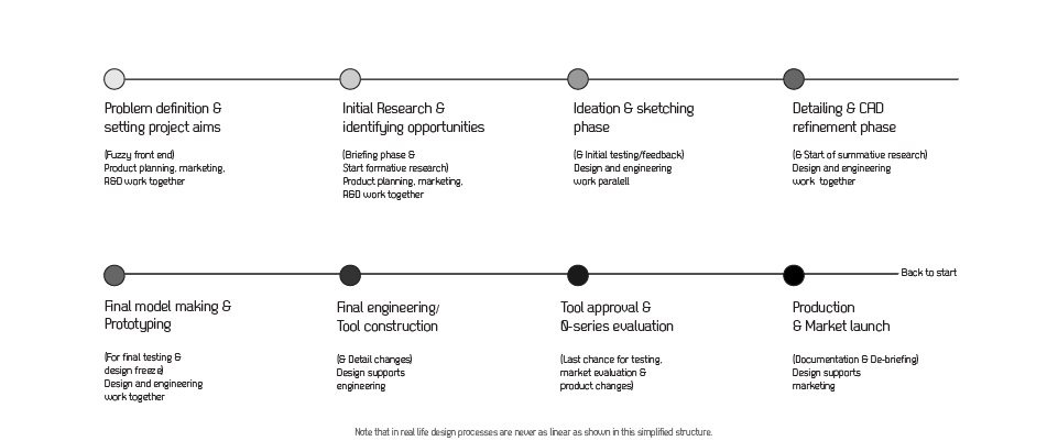
Extensive field observations, user and secondary research was conducted on Auckland’s current public transport system, global trends, technical innovations and comparable case studies. These were converted into system concepts and technical/ergonomic layouts for interior and exterior design ideation. Sketching, rough mock-ups, models, design renderings, CAD and animations were tools during the concept and detailing phase.

The project was presented to the public several times and feedback converted into iterations from SlimRide1 - Slime Ride3. The focus also shifted from a solitary system towards a solution which feeds bigger rail and bus hubs. Watch video documentry...

  • Initial idea sketch Initial idea sketch After observing the traffic issues in Auckland Oliver Neuland produced an initital idea sketch around a extrem narrow, automated pod supposed to run next to the motorway.
  • System concept System concept The idea formed to react on limited space for infrastructure by a 1.2m wide, rail-based PRT system, halfing the corridore space of a regular light rail train.
  • Literature research & case study research Literature research & case study research Review of historic and competitor solutions as well as investigations into the wide knowledge base around global and local public transport and PRTs was conducted.
  • Mindmap Mindmap Collection of infrastructure, issues, users and stakeholder involved in overall system.
  • User interviews User interviews Formal and informal interviews with potential target users and rail experts were conducted continuously.
  • Scenarios Scenarios Several scenarios were build and visualized via video. Image shows 2nd version of cabin design.
  • Ergonomics & volumetric studies Ergonomics & volumetric studies Among others tests, various seating and standing arrangements were visualized and images used in interviews.
  • 'Seat box' 'Seat box' Tests of maximum capacity were conducted with a simple mock-up cage.
  • Barrier free Barrier free Interior of an early interior with special consideration around wheelchair access.
  • Wheelchair access test Wheelchair access test 1.2m wide space proved to be sufficient
  • Exterior considerations Exterior considerations The very short and tall cabin posses some interesting issues around achieving a dynamic, vehicle like look. The condensed train shape highlights the change in proportion and expression.
  • Mini foam mock-ups Mini foam mock-ups Paralell to sketching many small scale mock-ups were produced to test shapes in 3D. Here one of the very early ideas.
  • Iteration Iteration Design ideas were iterated further.
  • Interior structure Interior structure Consideration ealry on went towards using handrails a seating as support structure for panelling.
  • Merging exterior and interior ideas Merging exterior and interior ideas For a while exterior and interior ideas were persued parallel to allow a wide rande of different ideas to unfold.
  • Technical consideration Technical consideration After investigation into suitable components technical layouts were refined further.
  • Test-rig Test-rig Small scale test rig of the different track mouting options was produced. Funding constraints prevented a planed full scale rig.
  • Street crossings Street crossings Where tracks in concrete troughs (below ground) would intersect with road crossings a flexible gutter closes the gap in the road. The T-bar below the cabin pushes the gutter open.
  • Chaining Chaining Initially the cabins were considered to run seperatly, later also chaining (linking) them to longer trains were investigated.
  • Slim Ride Mk1 Slim Ride Mk1 CAD model of Mk1 used for renderings and animations.
  • Lounge interior Lounge interior A more integral and loungy interior started to form as ideation into Mk2 started.
  • Local inspiration Local inspiration Since very early on it was the aim to address and include local cultural heritage. 'Waka' carvings were investigated.
  • Patterns as structual elements Patterns as structual elements The idea emerged to use Maori pattern inspired elements in a structual manor. Aluminium foam as casing material was considered and discussed with experts.
  • CAD test CAD test Several tests in CAD were conducted to evaluate the concept of carving inspired elements.
  • Passenger and cargo use Passenger and cargo use Alternative exterior concept as passenger and cargo option. Here carving elements proved problematic from a design perspective.
  • Shift from overall system to hub feeder Shift from overall system to hub feeder A shift in thinking was triggered after consultation with rail experts. The system was now proposed as a option to feed larger transport hubs from local areas. New routes were identified like St. Heliers or Te Atatu.
  • Scenario: Mission bay Scenario: Mission bay CAD rendering showing the PRT along Mission Bay.
  • Mk2 Development Mk2 Development To address several issues with SlimRide Mk1. A re-design started.
  • Mk2 CAD Mk2 CAD Apart from various technical changes, the overall design shifted to a 'Waka' inspired overall shape (central keel) and a simplified tube-based pattern introduced as sub-structure.
  • Freight pod option Freight pod option Like in Dresden, Germany the use of a existing track infrastructure for inner city freight transport is considered within the SlimRide vision.
  • Concept sketch for interior seating Concept sketch for interior seating The idea was explored to offer fold out tables for electronic devices as part of the loungy seating.
  • Interior Mk2 Interior Mk2 Fold-up seating allows flexible use of space. The formed metal sheet seats are a reaction on fire regulations in trains. The loungy feels remained in the shape language, but unfortunatly not in regards of cushioning.
  • Seals folded up Seals folded up The folded up seats allow space for a wheelchair - even though being tight.
  • Side view - explained Side view - explained The SlimRide Mk2 concept explained in detail.
  • SlimRide Mk2 on Dominion Road SlimRide Mk2 on Dominion Road CAD rendering in situation. A potential rubber wheel-bases PRT like used in Rome, Italy or Metz, France is considered to aviod underground tracks.

How to get started

image

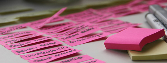
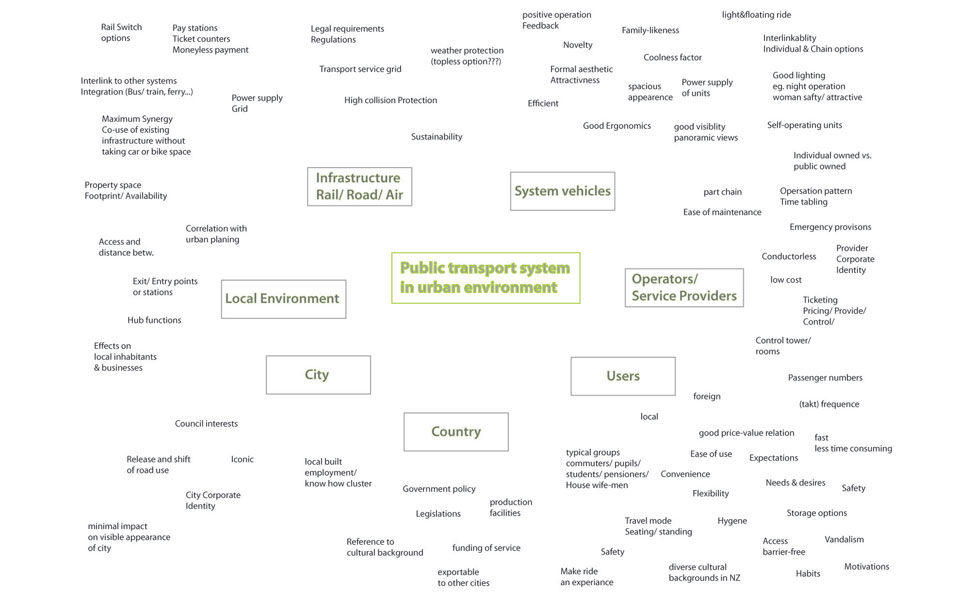
Note down some keywords around your project.
Use Mind map template to get started (download here). Additionally compile some visual material explaining
your project or inspirations. 

Summarize essential information about the project you envision. This can be simply re-styling a product or technical concept, idea visualization, new product development, identify opportunities through market and trend reviews or new technology or material use. See project brief as a guide.

 Get in contact with us to arrange an initial free consultation and quote. Feel free to propose what the work would be worth to you - we will look into reasonable proposals if the challenge is interesting to us.

Arrange a kick-off workshop with all parties/people involved in the project to collect all existing information, ideas, want and needs. Invite at least a representative of decision makers and strategic leaders, marketing, product planning, engineering (R&D), production/manufacturing and design team. 

This will enable a flying start with clear communication and already a pile of feasible ideas to work on and test. We are trained moderators and enable a efficient and result-driven use of the groups time together.

Mindmap Project Brief K-WorkshoP